


by Fred Eaton
Summary :
This article covers how to rebuild the MK3 rear master cylinder using one of our two rebuild kits.
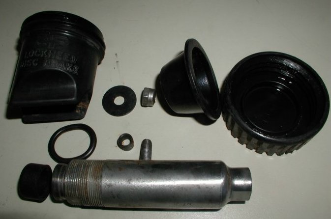
The first kit contains the normal parts that need to be replaced.
This kit is part number 19-4700,
$14.85.
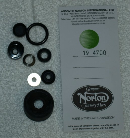
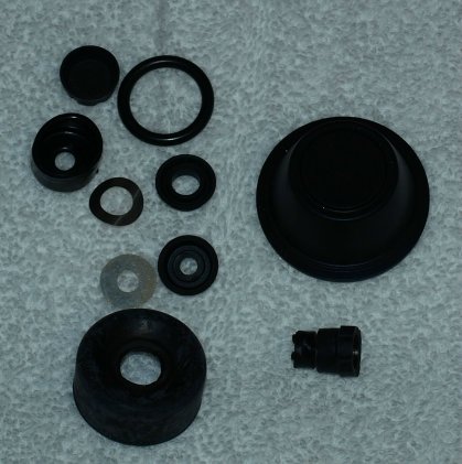
The other kit includes all the parts from 19-4700 and the Master Cylinder Bellows (06-1946) and the trap Valve (06-1944). This kit is part number 19-4700/R, $24.60.
Procedure:
First,
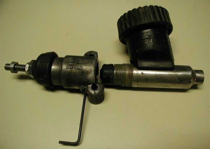
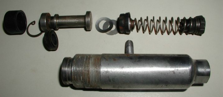
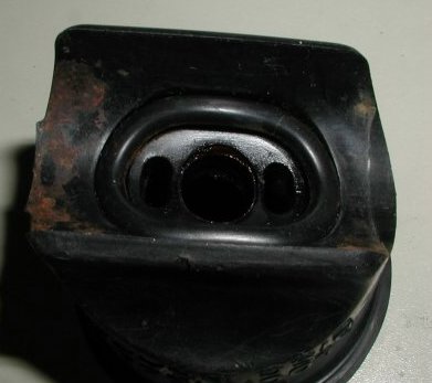
you will dismantle the master cylinder. The next picture shows the general assembly of the body to the cylinder.
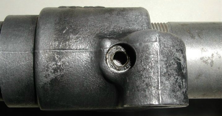
You can see there is one set screw, that takes a 3/32 allen wrench, that needs to be removed before you can unscrew the cylinder from the
body. The black plastic reservoir is removed by unscrewing the lock nut on the cylinder stud.
The innards of the cylinder are removed by removing the outer rubber cover and the circlip under this cover. If all goes well the piston
will pop out when you remove the circlip. You can then remove all the parts inside the cylinder.
If the piston does not pop out, spray contact cleaner and thoroughly clean the top of the cylinder.
Then press the piston in and let the spring push it back out; repeating this process should eventually get the
piston to stick out enough that you can get a hold of it and work it all the way out.
Be careful not to damage the piston because at this time new ones are not available.
Second, thoroughly clean all parts making sure the cylinder bore is smooth and clean, the piston's three holes are open and clean, etc.
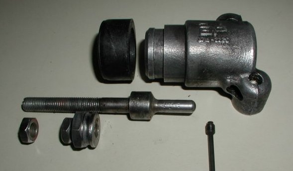
Third, Assemble the body. The body consists of the body, rubber end cover, push rod, large jam nut/cover holder, two small jam nuts and set screw. Put the push rod in the body and thread the large jam nut/cover holder and one of the smaller jam nuts on to the rod. These jam nuts are threaded almost all the way to the end allowing enough play to let the push rod move through its full travel. The other jam nut is used to secure the adjustment clevis (06-6265). Place the rubber end cover on the large jam nut/cover holder, but not on the body at this time.
Fourth, assemble the inside of the cylinder. Push the cup with the larger hole in the center (the other cup is not used) on to the piston with the flat top against the end of the piston as shown in the following picture. Push the valve into the end of the spring. Insert the spring into the cylinder with the valve going in first. Insert the solid rubber cup into the cylinder with the flat side facing out and the cup side against the spring. Place the two washers on top of the rubber cup with the flat washer against the cup. I have seen two spring washers on some cylinders, but the kit comes with one flat and one spring washer. I don't think it matters which direction the spring washer is inserted, just that it is against the piston end with the three holes. Insert the piston with the end with the three holes going in first. Lock the piston in place with the circlip. Place the rubber end cover on the end of the cylinder.
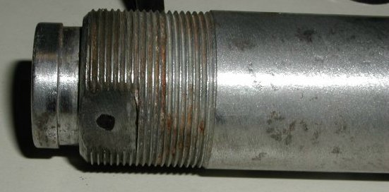
Fifth, assemble the cylinder to the body. Note: there are two flats on the sides of the threads of the cylinder. You should see a mark on the flat opposite the cylinder stud where the set screw presses against the flat. I blacken this mark with a black marking pen so I can thread the cylinder into the body to the exact depth it was before. You will be able to see the mark through the set screw hole. IF YOU THREAD THE CYLINDER IN TOO FAR, IT WILL NOT LET THE BRAKE PADS RETURN TO A NEUTRAL POSITION AND LOCK UP THE BACK WHEEL. Insert the set screw and tighten.
Sixth, place the reservoir on the cylinder. Place the spacer on the cylinder stud. Place the o-ring in the bottom of the reservoir. Place the reservoir on the cylinder with the reservoir angled towards the body as shown in the first picture. Place the reservoir washer over the stud and secure the reservoir with the lock nut.
This page was written and designed by F. H. Eaton & Associates if you have any questions or comments please contact us at eaton@oldbritts.com