


Introduction
Because of the higher current being produced, a matched pair of Zener Diodes are
employed to conduct the surplus current to earth under low load conditions.
Also, the existing wiring from the Rectifier to the Zener Diode, Ignition Switch
and Fuse may not be adequately rated and we have therefore supplied replacement
wiring of these in the kit.
When the new Rectifier and Zener Diodes have been mounted, it will be necessary
to cut the wires to length and fit the terminals supplied. It is important to
make sound, low resistance connections. If you do not have the correct crimping
tools, solder the wire to the terminal or take it to an auto-electrician.
Fitting
2. Mount one of the new Zener Diodes to an identical heat sink as the existing
one. It is important that the Zener is fixed to a flat, machined aluminium
surface and it is advisable to lightly smear the joint face with silicone
grease. The correct tightening torque is 2.0-2.3 Ib.ft. (0.3 kg.m.).
3. Discard the existing Zener and replace it with the other new one. The
motorcycle can be used at this stage by connecting the original wiring onto
this Zener Diode. NOTE Once Stage 4 is started, you cannot use the
machine until completion.
4. Mount the new 3-Phase Rectifier ensuring that it makes a good earth to the
frame. When tightening the nut, the Rectifier must be held by a spanner on
the 2 flats at the top. It must not be held by the plates as damage will
occur if they turn.
5. Fit the wiring supplied, to the large spade of the Rectifier. Run the 2
brown wires to the Zzener Diodes via a route where they can be taped to the
existing loom. Ensure that these wires will be equal in length within
100 mm (4") before cutting.
6. Disconnect the battery earth. Run one brown-blue wire to the Fuseholder,
cut to length and connect. Run the other brown-blue wire to the Ignition
Switch, cut to length and connect in replacement of the existing brown-blue.
Examine the manufacturer's wiring diagram. On some models the brown-blue
must go to the Ammeter, not directly to the Fuseholder. Use 28/0.3 mm. wire
from the Ammeter to the Fuseholder.
7. Remove the old Stator and the Rotor nut. Line up the Rotor Timing Mark with
a fixed point and remove the old Rotor, slide on the new Rotor and check
that the Timing Mark aligns exactly. Fit the new Stater and check that the
Rotor will lie approximately centrally within it. Use the washer supplied
if necessary. On some machines the Rotor nut has a cylindrical section to
go in the rotor and if the bike originally had a wide Rotor it is essential
to check that the nut does not bottom against the shaft before clamping the
new Rotor. If necessary turn or file the nut to prevent bottoming. Before
finally securing the Stator ensure there is 0.45 mm. (18 thou.) clearance
between each pole piece and the Rotor.
N.B. If necessary, waist the studs or bolts slightly to achieve this
clearance.
8. Cut the green wire supplied to the same length as the two existing harness
Alternator/Rectifier wires. Fit lucar and cover. Tape all three together
and connect to Rectifier and Alternator. They can fit onto the Rectifier in
any order.
9. Reconnect the battery earth with the ignition switched off. If any current
flows when this connection is made there is a fault which must be rectified
first.
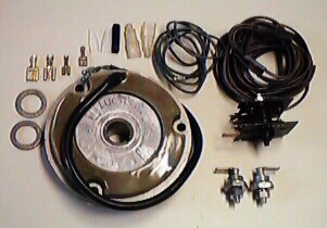 This picture shows what is included in this kit.
The following information is taken from the fitting instructions provided
by Mistral Engineering.
The High Output 3-Phase Alternator is a development by Lucas Electrical Ltd.
to achieve a high charge rate at low R.P.M. Used in conjunction with the
correct control circuit, this Alternator will replace any Lucas Aternator of
the same physical size (e.g. RM 19, RM 21 etc.). The Aternator produces 180
watts (at 12.5v.) and 85% full output is produced at 2,400 R.P.M.
1· DO NOT remove the existing Alternator at this stage.
This page was written and designed by F. H. Eaton & Associates if you have any questions or comments please contact us at info@fheaton.com