


This was the original Power Arc ignition system that we sold and most of the information in this article still applies to our latest Ignition (see Our new Latest Ignition).
Old Britts has been looking for an electronic ignition to replace the Boyer ignition that we have sold for many years. The Power Arc far exceeds our wish list for a better ignition system for Commandos. The list of the Power Arc features that we are presently offering:
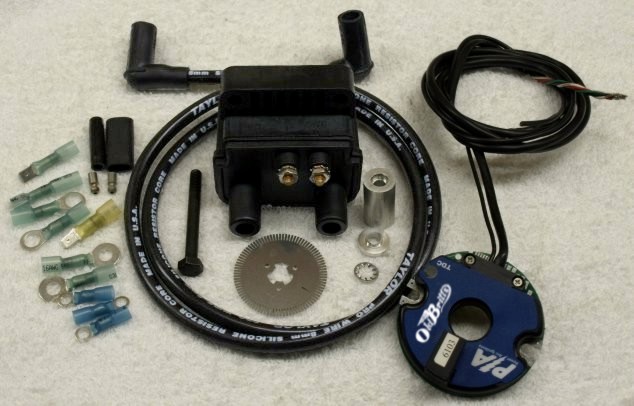
- No external module. The complete unit fits in the points compartment.
- Low voltage operation. This ignition will work down to 6 volts. This is extremely important for electric start Commandos.
- Sparks three times each compression stroke. This provides a very efficient and clean running engine.
- Very easy to install. No need to run the engine up to 5000rpm to time the ignition. Just find top dead center (TDC), rotate the stainless encoder disc until the static LED timing light comes on, lock the disc down and you are done.
- Has a precision rev limiter built into the module. Old Britts pre-sets this to 6800rpm, but can be set to whatever the customer desires when ordering.
- Two switchable advance curves (maps) are available with each unit.
- Automatic coil safety shutoff.
- Will run with a positive or negative ground.
- Uses less energy than points.
- Has an electronic tachometer output.
- Programmable.
- Made in the USA.
Old Britts can offer more features for the Power Arc ignition.
These additional features are: a single fire ignition using two separate coils, up to four
ignition maps, the ability to programming the ignition on the bike and more.
Power Arc options for its Advanced Electronic Ignition
These additional features will be mainly used by racers. The dual fire, two maps version we are currently offering is more than adequate for 99% of our customers.
Old Britts has developed two advance curves (maps) that we feel provide a good all around riding experience for our customers. We developed these maps on our engine dyno.
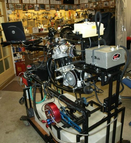
We are going to keep testing our advance curves on our dyno and road testing with different engines and engine combinations. If in the future we come up with new ignition maps that we feel some customers may want, Old Britts will re-program your ignition for free.
Our advance curves are dyno tested and now race tested by Kenny Cummings. Click in Kenny's picture below and watch his 750cc Norton smoke the 1000cc vintage superbikes at Virginia International Raceway:
Old Britts has only developed ignition curves for Norton Commandos and will only support this ignition for Norton Commandos. This ignition is avalible for most other British makes through C5 Performance Inc.
SPARK PLUG WIRES
Choice of spark plug wires is an important consideration when using an electronic ignition system. You must use
resistor spark plug wires (carbon core or spiral wound with at least 800 ohms per foot).
Other spark plug wires will damage the ignition module and void the warranty!
SPARK PLUGS
You must use a resistor spark plug with electronic ignitions. Spark plug gap should be limited to as small as possible,
while still maintaining performance.
A wide spark plug gap can cause the following problems: Hard cold starting, misfires during rich or lean fuel
conditions, and reduction of upper rpm range.
Initial settings for spark plug gaps should be set at 0.025".
Many things affect spark plug gap settings:
- Compression Ratio: The higher the engine compression, the more voltage required to fire the plug, and the narrower the plug gap should be.
- RPM: The higher the rpm's the less time the coil has to charge to break over voltage or complete saturation. A narrower spark plug gap will help high rpm stability.
- Multi-Spark: To maintain a good secondary spark within a wider rpm range it is wise to run a narrower spark plug gap. It is better to precisely place two stable, consistent sparks than to fire one wider spark that may cause misfires in rich or lean conditions, or from any of the above reasons.
INSTALLATION STEPS:
Do not use solid or spiral wound suppression spark plug wires,
use resistor wires only. Failure to observe these precautions
WILL DAMAGE IGN. & VOID THE WARRANTY.
- Turn the ignition switch OFF. Remove and replace the existing ignition coil with the Power Arc dual fire
coil.
The installation of the duel fire coil and setup of the spark plug wires is covered in the
12V Power Arc Coil, Coil Mounting Kit and Plug Wires documentation.
- Remove the old contact breaker plate or electronic ignition stator from the points compartment on the timing cover. Keep the Pillar bolts (06-1281) for they will be used in step 4.
- Remove the auto advance or the electronic ignition rotor.
You will need a puller or the factory slide hammer (06-4298) to remove the auto advance.
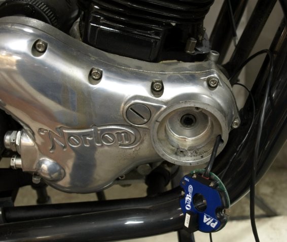
The points compartment with the ignition module and just starting to thread the wires. - Insert the ignition module into the points compartment. Thread the ignition wires through the hole in
the points compartment.
Tighten down the ignition module using the pillar bolts that you removed is step 2.
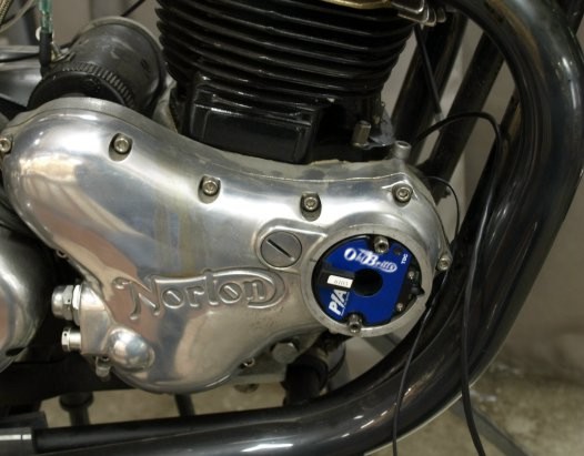
The ignition module installed in the points compartment. - Connect the ignition module wires (Black and Red wires) to the coil as shown in the following
two wiring diagrams.
The two terminals on the coil are not polarity sensitive, so the Black and Red wires can go on either
terminal.
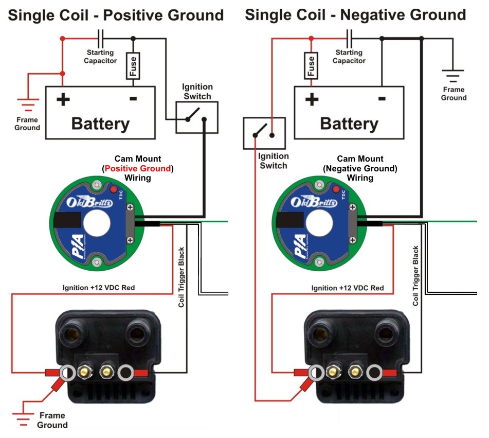
The Red ignition module wire is used as the +12 VDC to the module. The Black ignition module wire (in the module wiring harness) is used as the coil trigger.
Never touch this black trigger wire to +12 VDC for it will blow out the transistor and void your warranty.The wires coming from the ignition module are longer than needed. You may shorten them some, but keep in mind, that after you crimp the wire connectors to the end of the wires, they will not fit back through the hole in the points compartment. If for some reason you need to remove the ignition module or remove the timing cover, you will have to cut off the wire connectors and shorten the wires for the next installation. It is best to route the module wires so that they look good, but keeping extra length for the future.
The #10 ring terminals supplied with our Wire Connector Kit are the crimp, shrink and solder types. What you do with this type of terminal is first crimp it on to the end of the wire and then using a heat gun, shrink the terminal end on to the wire. There is low heat solder inside the terminal and when heat is applied to shrink the end of the terminal the solder melts and solders the terminal to the wire. If you do not have a heat gun, we highly recommend purchasing one. It will come in handy for a number of jobs from heating a case before pressing in a bearing to heating a stubborn bolt or nut.
- The separate Black ignition module wire is used as the -12 VDC to the module.
- For positive grounded Commandos (common on most Commandos), connect the separate Black wire from the ignition module to the -12 VDC wire coming from the ignition or kill switch. This is a White, White/Blue or White/Yellow colored wire on most stock wiring harness.
- For Commandos converted to negative ground, connect the separate Black wire from the ignition module to frame ground. The easy way to connect this wire to ground is: do not thread it through the point wire hole, but to cut it short enough to attach a ring connector to the end and connect it to one of the pillar bolts holding the ignition module in place.
- The White ignition module wire is used to select one of the two ignition curves (maps).
When this wire is connected to -12 VDC the standard curve is used by the ignition module.
When this wire is not connected to anything the more aggressive curve is used by the ignition module.
This wire can be connected to an optional switch that has the other side of the switch connected to -12 VDC.
If you are not using a switch, connect the White wire to -12 VDC.
- For positive grounded Commandos, connect the White wire to the same wire you connected the separate Black wire to in step 6.
- For negative grounded Commandos, connect the White wire to frame ground.
- Hook the green wire to the electronic tachometer trigger wire if used. If not being used with as a tachometer trigger, tape off the end of this wire.
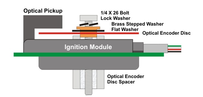
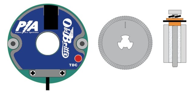
- Prepare the encoder assembly by placing the flat washer onto the stepped brass washer and press this into the optical encoder disc centered on the step in the washer. Place the internal tooth lock washer onto the 1/4 x 26 bolt and thread this through the brass washer.
NOTE: The bolt enclosed is for stock cams with 1/4 x 26 Whitworth threads. Some aftermarket cams use a 1/4 x 28 SAE thread. If the bolt does not thread into the cam easily by hand, DO NOT USE A WRENCH TO TIGHTEN, since the cam may require a different bolt. If you are having any doubts, call us before you break the bolt off inside the cam. 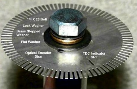
The encoder disc assembly showing the order of the assembly. - Insert the encoder disc spacer through the center hole of the ignition.
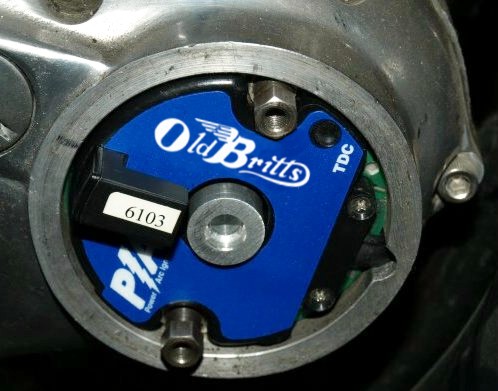
The encoder disc spacer in place. - Place the encoder assembly through the Ignition center hole.
Lightly tighten the bolt, but allowing the encoder disc to rotate with some pressure.
You can apply pink Loctite to the bolt, but we find that the lock washer will hold the encoder assembly in place.
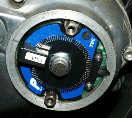
The encoder disc installed. - Rotate the engine to TOP DEAD CENTER (TDC).
This can be accomplished in several ways. We use a dial indicator inserted into one of the spark plug holes.
If you are very careful, you can use a rod long enough to stick out of the spark plug hole when the pistons are at bottom dead center.
The spark plug hole is at an angle with the direction of piston movement, so the rod can get caught as the pistons come up.
Rotate the engine till the dial indicator or the rod indicates the pistons are at TDC.
Since the pistons are at TDC for a period of crank rotation, we mark TDC by rotating the engine in one direction and then
rotating the engine in the other direction. We use half way between the two marks for our TDC.
If you remove the spark plugs and put the gearbox in 4th gear, rotating the engine is easier.
If the primary cover is off, you can rotate the engine by turning the alternator nut.
If the primary cover is not off, you can rotate the engine by turning the rear wheel.
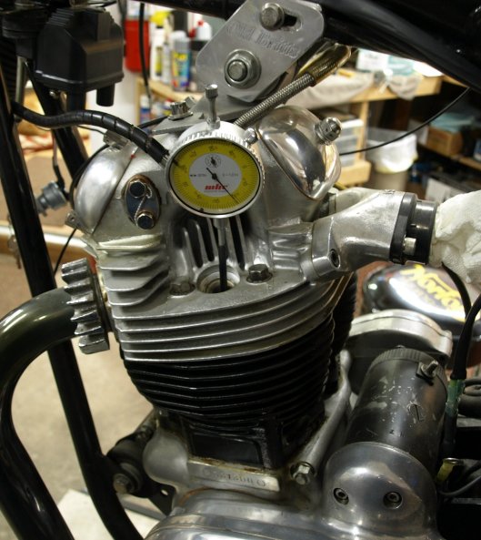
Using a dial indicator to find TDC. - Remove the Spark plug wires from the plugs, then power on to the ignition module. Rotate the optical encoder in the opposite direction of cam rotation until the static timing LED lights up. Holding the optical encoder firmly to hold the encoder wheel in place, tighten the contact breaker bolt. Rotate the engine to recheck TDC to make sure the timing has not moved. Note: The LED will turn on once for two crank rotations, since the cam rotates once for two crank rotations.
- Replace the spark plugs and wires.
- Start the Engine.
If you experience an occasional kick back when starting your bike it is because the ignition thought it was at a different position of the crank rotation than it actually was. The ignition will fire the first time after it is turned on when it sees Top Dead Center (TDC) then start counting teeth on the encoder disc to start the advance curve firing sequence. If you turn on the ignition and kick the engine through to find the position where you like to start your bike, the crank may slip backwards under compression a bit and the ignition does not know the engine is running in reverse and start to count teeth on the encoder disc. Then when you start kicking the engine the ignition will fire before the desired position and can cause kick back.
The recommended starting sequence is:
- With the ignition off, kick the bike through until you have the crank in the position that you normally like to start your kick.
- Turn on the ignition.
- Kick the bike over and always kick through the complete throw of the kick start arm. Do Not do a half kick since the kick start pawl does not disengage from the engine until the kick start arm has completed its rotation.
- If you turn off the ignition, the ignition will reset and look for TDC when it is turned on again.
The following is the Power Arc limited warranty for six months. Old Britts will extend this warranty for one year from the date of purchase.
P.A. Ignition Co., Inc. warrants to the original retail purchaser of a Power Arc IDS ignition that it will, free of charge, repair or replace at its own option, the product if returned to P. A. Ignition Co., Inc. within 6 months after purchase and if found by P. A. Ignition Co., Inc. to be defective in material or workmanship. This warranty is not transferable by the purchaser and shall be voided: if alterations not authorized by P. A. Ignition Co., Inc. are made in the equipment or if the serial number or date of manufacture has been altered, defaced or removed. Nor does this warranty apply: if the equipment has been subjected to accident, misuse, improper hookup, damaged by flood, fire, or act of God, or has been used on circuits or voltages other than those indicated in its instruction manual. If the equipment is found to be defective in materials or workmanship the equipment will be returned and P. A. Ignition Co., Inc. will pay the return shipping (this does not include next day shipping, second day shipping, shipments outside of the continental U. S. A. or shipments outside of the U.S.A.). All warranty work outside of the U.S.A. must include prepayment of return shipping. Customs, duties or tariffs are not covered by this warranty. If the equipment is found to be defective but is due to customer misuse (as described in warranty) P. A. Ignition Co., Inc. will notify the customer and if the customer wants the defective equipment returned P.A. Ignition Co., Inc. will return the equipment C.O.D. freight. If the equipment is found to be in operational order when returned to the factory P.A. Ignition Co. Inc. will return the module with a $25.00 service charge plus freight and C.O.D. Charges.
Any module returned under the warranty must include note of explanation of failure and be accompanied by a dated bill of sale.
P.A. Ignition Co., Inc. warranty obligations are limited to those set forth herein and no other obligations, expressed or implied, are assumed by P.A. Ignitions Co. Inc.
Some states do not allow the exclusions or limitations of incidental or consequential damages, or allow limitations on how long an implied warranty lasts, so the above limitations or exclusions may not apply to you. This warranty gives you specific legal rights, and you may also have other rights which vary from state to state.
This page was written and designed by F. H. Eaton & Associates if you have any questions or comments please contact us at info@fheaton.com