


The following is a reprint of the installation sheet supplied by Boyer Bransden:
Frindsbury House, Cox Lane, Detling. MAIDSTONE, Kent ME14 3HE ENGLAND
Telephone: 01622 730939 Fax: 01622 730930
BOYER BRANSDEN ELECTRONIC IGNITION SYSTEM FOR NORTON COMMANDO TYPE MK3
Comprising:-
a) Transistor box (rectangular black box with wires)
b) Stator plate (round printed circuit with two coils and wires)
c) Magnetic rotor (round plated steel unit with two magnets fitted)
d) Plastic strap
e) 1.25" x 0.25" BSF bolt 6r 1.25" x 0.25" UNF bolt
f) Terminals: 4 male bullets
Fitting instructions:-
1) Remove seat.
2) Remove tank, disconnect fuel lines
3) Remove contact breaker cover.
1) Remove complete contact breaker assembly including the auto-advance unit. Disconnect the two wires colored black-white and black.-yellow.
5) Set engine at 31 B.T.D.C. on the alternator mark (ensure correct mark is used - there are two marks on the alternator on 1972/3 models,
use the mark indicating T.D.C. with the pistons in top position).
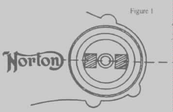
6) Fit magnetic rotor unit using one of the bolts (supplied), with the magnets in line with the "NORTON" name on the timing case. See Fig. l.
7) Fit stator plate (with the connecting wires at the bottom) using the standard studs.
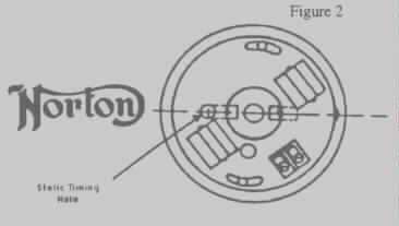
8) The magnet on one side of the rotor should now be in the center of the top timing hole in the stator plate; this should also set it half
way along its adjustment slots. If not, move the rotor until this is achieved without turning the engine from 31 B.T.D.C. See Fig. 2.
The atlas engine has the points housing behind the cylinder head. It's shaft is rotating in the reverse direction. Set the timing
on the clockwise timing hole.
9) Fit two male bullet connectors (supplied) to the two wires in the timing cover and plug them into the corresponding colored female
connectors on the stator plate wires. These connectors should be wedged in tight against the timing case or strapped to one of the stator
coils as they can fracture with vibrations. Check that the two ignition wires from timing cover to the front frame tube has a minimum
2 inch (50mm)
of free play.
10) The two wires in the timing cover can be traced up the frame tube to a pair of bullet type connectors. Remove these connectors.
11) Remove all the low tension connections from the two ignition coils.
12) Remove the white-blue wire from the ballast resistor between the two ignition coils. The color of this ignition power feed wire may
be different on some machines, if so check using a test light or meter to find the live (-12 volts) when the ignition is switched on.
The ballast resistor is no longer required and can be removed.
13) Remove the red wire from its earthing point on the end of the condenser pack. Reconnect this to the + marked terminal on the left-hand
ignition coil.
The condenser pack is no longer required and can be removed.
14) Fit the transistor (black) box to the frame tube with the plastic strap (supplied), with the long wires to the right-hand front side and the
two short wires to the left. See Fig. 3.
Old Britts makes a mounting bracket for the Boyer black box, see Boyer Black Box Mounting Bracket.
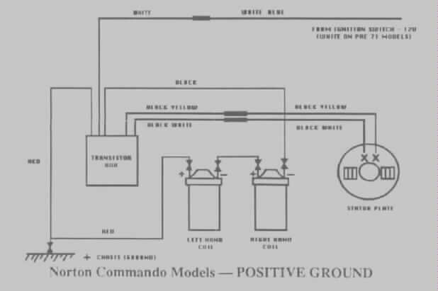
15) Connect the short black-white and black-yellow wires From the transistor box to the two wires which feed down to the timing cover,
using the male bullet connectors (supplied).
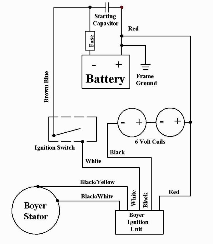
16) Connect the red wire from the transistor box as follows: first connector to the earth tag on the end of the condenser pack,
second connector to the + terminal of the left-hand ignition coil with the red wire already connected to it.
17) Connect the - terminal of tile left-hand ignition coil to the + of the right-hand coil using the short black connecting wire.
18) Connect the black wire from the transistor box to the - terminal of the right-hand ignition coil.
19) Connect the white-blue wire (the one removed From the ballast resistor) to the white wire from the transistor box.
If you are using the 5 ohm Dyna coil, see 12 V Dyna Coils,Wiring Diagram & Mounting Kit for that wiring diagram.
20) All original wires that have been removed are now not in circuit and can be safely tucked out of the way.
21) Check all connections are good and tight, if not remove and tighten with pliers.
22) Refit tank, fuel lines and seat.
23) Start engine and time with a stroboscope to 31 B.T.D.C. (28 DEG. with standard ignition) with the engine running up to 5000 R.P.M.
This is done by moving the ignition stator plate (Stator: clockwise to advance and counter-clockwise to retard).
If the timing is not obtainable before the end of the adjustment, the magnetic rotor will have to be slackened off and moved a small amount
(Rotor: counter-clockwise to advance and clockwise to retard) until the correct timing can be obtained.
24) Refit timing cover. With this system two 12 volt coils can be used as long as they are in good order. The standard 6 volt coils do short
out to the metal case, check for damage by mounting clamps. A single duel output coil can be used as long as its primary resistance is more
than 3 ohms. This should be mounted on the frame in a manner that will take the heat from the center core.

This page was written and designed by F. H. Eaton & Associates if you have any questions or comments please contact us at info@fheaton.com