


Updated 04/13/11
This installation documentation along with companion check lists, (see Starter Conversion Check Lists) will contain all the steps required to perform the conversion.
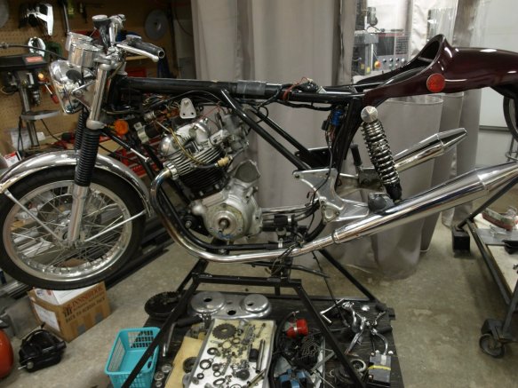
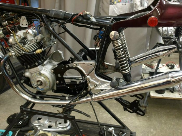
The first phase of the conversion is to remove the engine cradle and the swingarm. See the first phase check list removing the engine cradle and swingarm for what is involved to accomplish this phase. The following picture is what the bike looks like at the end of this phase.
You will need to remove your swingarm from the engine cradle and our technical article Removing the swinging arm spindle will help accomplish this task.
- The second phase is preparing the parts to be sent to Old Britts. You will need to ship your inner and outer primary cases and possibly some other items that you will want modified by Old Britts. See the second phase check list Preparing parts to send to Old Britts for modification., for a list of the parts that may need to be shipped and a list of required parts that may need to be ordered.
- This is also the time to think about upgrading your swingarm lubrication system (see Modify Customers Swingarm for MK3 Lubrication. If you decide to do the lubrication system, you will also have to ship your swingarm to Old Britts.
- You will need to modify your battery box to fit around the starter motor. See our article Modify Customers Battery Box for Starter Upgrade for the information on this procedure.
- You may also want to think about upgrading your rear isolastics to the MK3 vernier adjustable isolastics, if you have not done so already. If you were to install the rear MK3 isolastics, you would have to remove the engine cradle, and since we will be sending you a new engine cradle modified for our starter, you might want to purchase the rear MK3 isolastic conversion kit (see 06-7117) at this time. We will install the isolastic upgrade in the new engine cradle at no additional charge.
- The third phase is mounting the swingarm onto the engine cradle and then re-assembling the engine cradle onto the bike. See the third phase check list Mounting the swingarm onto the engine cradle and re-assembling the engine cradle onto the bike.. We want to note here that anytime you are threading a stainless steel nut on to a stainless steel bolt, it is good practice put a dab of anti-seize on the threads. Stainless has a tendency to work harden and weld itself together.
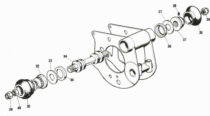
We are installing the MK3 vernier adjustable isolastics into the engine cradle for this bike. The instructions that come with the MK3 rear isolastics and the exploded view above show the abutment (37), with the set screw (26), on the fixed end and on the right side. In most cases it would not matter which direction you insert the bonded rubber shaft (34), but with our starter, DO NOT mount it as shown above. You want the adjuster (22) on the right, since the starter motor does not allow enough room to easily work the adjuster if it is on the left. The end of the shaft where the threads do not go completely to the end of the shaft is the fixed end. The set screw when tightened will press against the un-threaded part of the shaft. Before pressing the bonded rubber shaft into the engine cradle, make sure the inside of the tube is clean and smooth. We apply a very thin film of grease to the inside of the tube, just enough to help the rubber bushings on the shaft slide into the tube. Start the first rubber bushing by hand to get all the leading edge into the tube. Press the shaft into the tube with an equal amount of the threaded ends sticking out of the tube. Place the end cap (36) over end of the tube on the fixed end and the PTFE washer (23) up next to the end cap. Thread the abutment on to the fixed end of the shaft and if it runs out of thread just as it snugs up against the PTFE washer and end cap, allowing the PTFE washer to rotate, the shaft is in the proper position.
If you are not using the MK3 isolastics, remove the isolastics from your old engine cradle and insert them into the new cradle.- Mount the swingarm on to the engine cradle. We are making the swingarm lubrication changes and mounting a pre-MK3 swingarm onto the new engine cradle. See our article Installing the MK3 swingarm lubrication system and swingarm on the engine cradle for information on this procedure.
- You can now insert the engine cradle and swingarm back into the bike. We did not screw the abutment and adjuster on to the MK3 isolastic shaft,
since that did not allow us to fit the engine cradle past the frame.
This customer is upgrading the engine bolts and the rear mounting stud to stainless steel so we
placed the old rear mounting stud temporarily through the engine cradle to hold it in place. We will be pulling the
mounting stud in and out a couple of times and only the final time will we use the new stud. We actually added a slight taper to one end of the old
stud to help in threading it through all the frame parts. When we finally insert the new stud, we will have the old stud in place and
back the old stud out at the same time we insert the new stud.
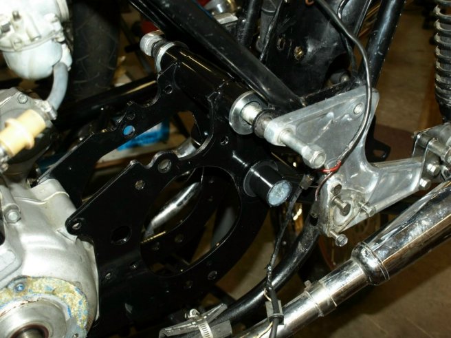
Engine cradle temporarily in place. - To prepare the adjuster and abutment for installation, just start the set screw into the abutment, then place the adjuster and abutment into the
rubber boots (35) with the PTFE washer on top.
Move the lip of the rubber boot down on the adjuster and abutment and put the spring clip (21) over the adjuster as shown below.
Adjuster and abutment ready to install. - Remove the mounting stud and drop the engine cradle enough to be able to thread the abutment on to the fixed end of the isolastic shaft. Just get the abutment started on the shaft, then move the rubber boot over the end cap and screw the abutment tight on the shaft. Tighten the set screw on the abutment with a 3/32 allen wrench.
- Screw the adjuster on to the isolastic shaft. Make the adjuster as tight as you can, we will set the gap in the isolastics later.
- Reposition the engine cradle and insert the rear mounting stud.
- Insert the stepped washers 38-600207 into the lower engine cradle mount and insert the lower engine bolt at this time. The lower engine bolt will not clear the frame, but without the other two bolts in place and the head steady removed, a bar under the engine will lift the engine just enough to insert the lower engine bolt.
- Since the gearbox can be inserted into the engine cradle with the cradle bolted up to the engine, insert the other two engine bolts and tighten up all three bolts.
- Insert the new rear mounting stud, if you are replacing the mounting stud. Do not tighten it up at this time.
- The fourth phase will install the starter motor, wiring and test the wiring. See the fourth phase check list Installing starter and testing the wiring for more detail on this phase.
- Install the gearbox, oil junction block and if applicable the 1972 crank case breather.
The oil junction block installation is straight forward, but the 1972 breather housing can be a bit of a problem due to limited access.
The breather body is fastened to the crank case with two 1/4" bolts (06-7951). The bolts are kept from coming loose by two
tab washers (06-3418). We find it easier to bend the thin tab 90 deg. and the wide tab slightly prior to installing.
The thin tab fits over the housing and the wide tab over the bolt head.
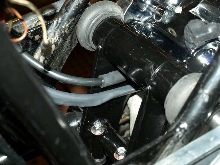
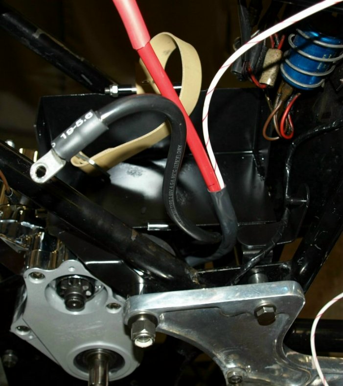
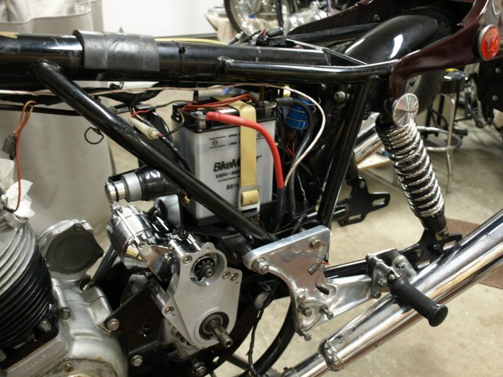
The bike ready for the starter installation. - Place the starter motor on the engine cradle by threading the two wires attached to the motor through and under the
Engine cradle so they can come up between the battery box and the frame.
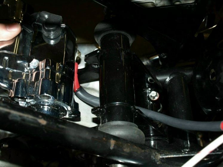
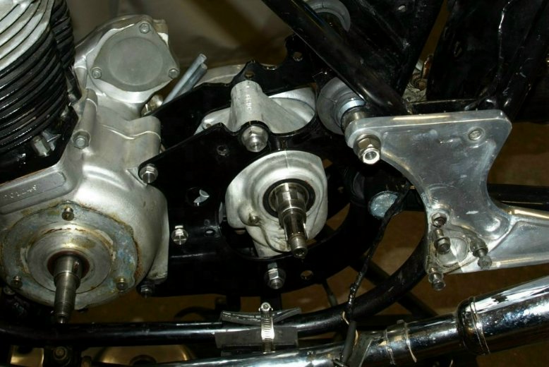
Threading the starter wires. - The starter has three screws holding the bendix access plate to the starter. The engine cradle has two holes drilled
into the right side to allow clearance for two of the screw heads. When the starter is properly installed, the access plate is
flush with the right side of the engine cradle as shown in the next two pictures.
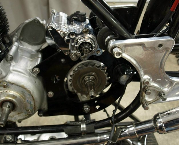
The left side of a properly installed starter. 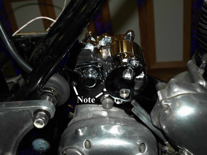
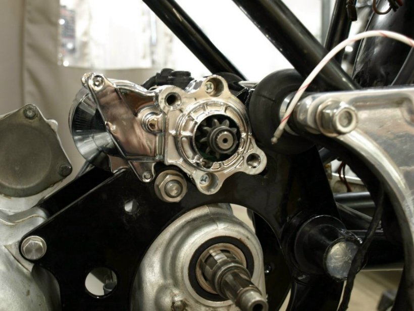
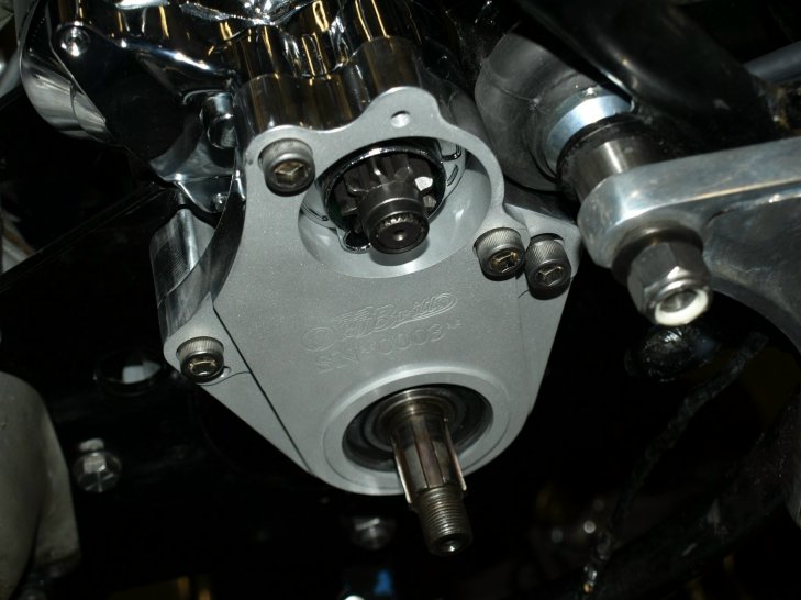
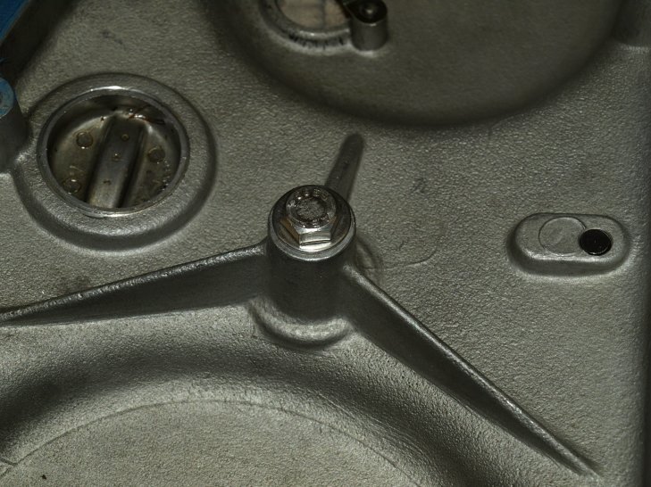
The right side of a properly installed starter, note the screw heads seen through the engine cradle. - Install the counter shaft sprocket. This sprocket cannot be greater than a 21 tooth sprocket.
A 21 tooth sprocket installed on the gearbox. - Install the starter bracket on to the gearbox main shaft and secure to the starter motor and the engine cradle by:
- Thread the two 3/8" x 24, 1" long bolts into the starter motor till the bolt head is well into the starter bracket recess, DO NOT TIGHTEN.
- Thread the two 3/8" x 24. 2 3/4" long bolts into the engine cradle enough that you can place the washer and nut on these bolts.
- Tighten up the two long bolts.
- Tighten up the two short bolts.
- Remove the nut off the rear long bolt, so the black ground wire can be installed in the next step.
The starter bracket with the four allen bolts started. - Install the black ground wire on the rear bracket mounting bolt and tighten all four mounting bolts.
Where the ground wire (top wire) is installed. - Install the battery box making sure the three starter wires come through the opening between the top two "Z" bracket mounting
bolts and the battery box and the frame.
The battery box and starter wires installed. - Mount the back air box plate, if being used, to the battery box and the frame.
- Install the new battery into the battery box on top of the rubber battery tray and secure with the battery strap. The strap should be tight, but not so tight that it is hard to fasten the buckle over the hook.
- Hook up the three starter wires.
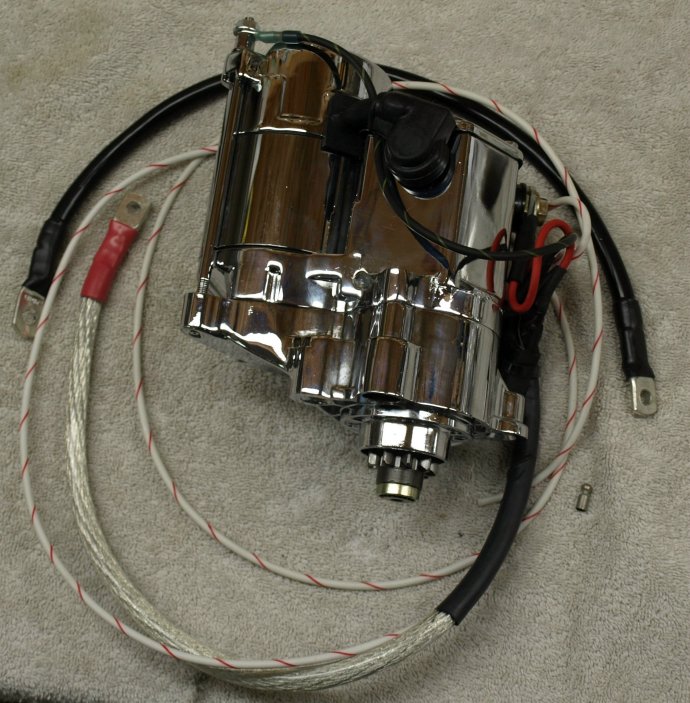
The wiring harness along with the starter. The starter battery wires are color coded for a negative grounded system, but by following the information below all will work correctly. This harness consists of the following:
- One red #4 gauge wire that connects the power to the starter.
The 5/16" lug connects to the threaded lug on the starter. We will make this connection prior to shipping.
For positive ground systems the 1/4" lug connects to the negative side of the battery.
For negative ground systems the 1/4" lug connects to the positive side of the battery. - One black #4 gauge wire that grounds the starter motor.
The 3/8" lug connects to the rear starter bracket allen bolt. The bolt is threaded through the starter bracket and through the engine cradle. The lug is threaded over the end of the bolt that sticks out from the inside of the engine cradle.
For positive ground systems the 1/4" lug connects to the positive side of the battery.
For negative ground systems the 1/4" lug connects to the negative side of the battery. - One 4 foot long #14 gauge white/red wire that connects to the starter button.
This wire is pre-attached to the starter with a male bullet connector on the other end.
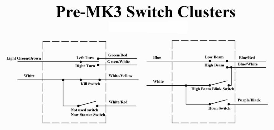
Pre-MK3 switch cluster wiring diagram. If you are using the stock switch clusters, one button is not normally used. This button is on the cluster with the turn switch. This cluster is normally found on the left side, with the un-used button on the bottom, however you may find this button on the top or on the right side. Trace the cluster wires to where they plug into a bunch of wires under the gas tank. Find the white/red wire and unplug the wire coming from the connector, leaving the connector pluged into the wire coming from the switch cluster. Thread the white/red wire from the starter through the frame and plug it into the connector.
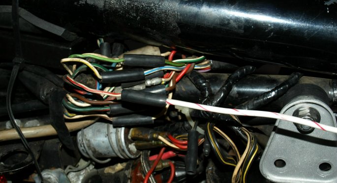
The white/red wire connection under the gas tank. - Make sure the fuse has been removed from the fuse holder and install the ignition switch, the power wire and ground wires to the battery.
- The starter can be tested at this stage. Place the fuse into the holder, turn on the ignition key and press the starter button.
If all was done correctly, the starter gear should have moved outward from the starter and spun in a clockwise direction.
The starter motor ready for testing.
Fifth Phase - The fifth phase will complete the installation of the primary drive and test turning over of the engine. See the fifth phase check list Installing the primary drive for more detail on this phase.
- Thread the rear chain through the starter bracket and back to the rear of the bike. Since the inner primary cover is to be installed next, the gearbox sprocket is easly accesable, making threading the chain over the gearbox sprocket easy.
- Install the inner primary case. As listed in the check list, Blue Loctite 242 is applied to all five fixing screws.
The Loctite is not applied to the front three screws for securing purposes, since they have tab washers to secure them,
but to prevent oil from seeping into the primary case. The Loctite is used for securing the two countersunk screws that thread into
the starter bracket.
The inner primary case installed. - If your new belt drive clutch basket did not have a new clutch center installed, remove your clutch center from your old
clutch basket and install in the new clutch basket.
Please Note: prior to installing the clutch center, you need to verify that the tab washer (06-3459) does not interfere
with the new clutch basket.
In some cases the tab that fits through the clutch center is too long and will rub against the clutch basket.
If this is the case you need to be file it down so it will be flush with the inside of the clutch center.

The tab sticking through the clutch center. Since you can not determine if the tab is too long when the clutch center is installed you will need to check it prior to installing. If you purchase a new clutch center and had Old Britts install it in the new clutch basket, a tab washer that fits will be included.
- Install the new clutch basket and verify that it does not rub on the inner primary case. The clutch basket needs to be as close to the inner primary case as possible so the belt alignment is correct, but if the ring gear is too close to the starter, the starter motor will not start. The starter motor has the starting solenoid built into the starter gear. When you press the starter switch, the starter solenoid moves the starter gear out towards the ring gear and then connects the battery to the starter motor turning the starter gear. If the starter gear is stopped from connecting the battery to the starter motor by the ring gear, all that happens is the starter gear taps the ring gear. This alignment is checked by Old Britts on its mockup prior to shipping. Any and all spacers required will be included and labeled.
- Install the drive pulley, belt and alternator rotor. Please Note: The thick rotor spacer (06-0402) is not used with our
drive pulley.
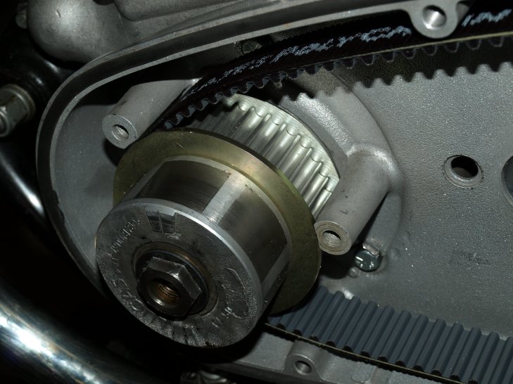
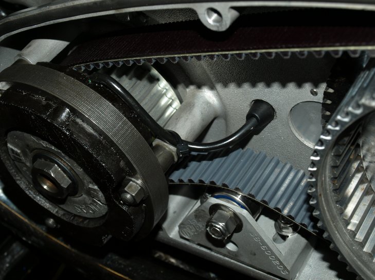
The drive pulley installed. - The belt tensioner may come with one or two shims, depending on what Old Britts is producing at this time.
At this time two belt tensioners, a 2" and a 2 1/4", are being produced and two shims, 1/8" thick and 1/4" thick.
Old Britts will determine what is required on our mockup and as things iron themselves out, only one belt tensioner,
not requiring a shim may be produced.
The important thing about the Old Britts starter is the tension on the belt. When the bike is running, the tension on the belt is at the top of the belt. When the starter is starting the bike, the tension is on the bottom of the belt. Because of the high torque of the starter motor, if the belt is lose, the belt will be slapped against the belt tensioner and can cause the belt to break. We have found that the correct belt tension is when the bottom of the belt is very tight against the tensioner and you can just twist the top of the belt about 45 degrees.
If shims are included, place them on top if the tensioner bolt holes.
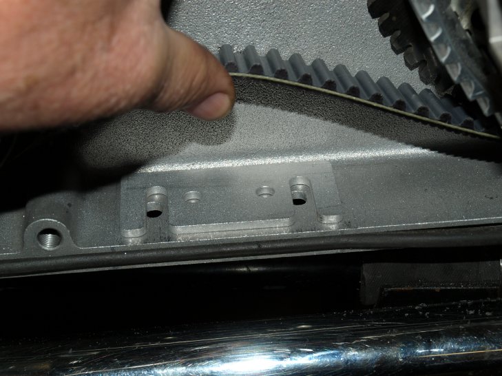
One shim in it's proper position. Place the belt tensioner on top of the shims. You may find it easier to place the tensioner under the belt and pull up the front of the tensioner and slide the shims one at a time under the tensioner. Thread the two 1/4" bolts from the bottom through the belt tensioner and tighten.
- The starter can be tested at this time to verify that it will turn over the engine.
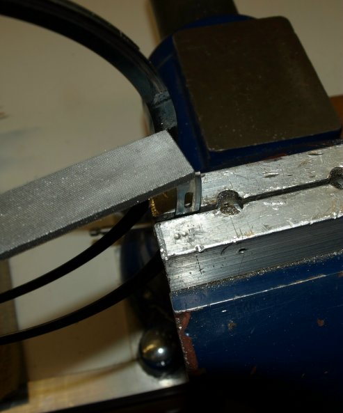
Primary drive read for testing. - Install the clutch plates, diaphram spring (06-0770) and the spring circlip (06-0751). In most cases the older spring
circlips are a bit too long and will not fit fully into the circlip groove.
In these cases the circlip will almost fit, but the end will ride up on the cross over part of the circlip.
File a bit of both ends until the circlip fits correctly.
Filing a too long circlip. - Install the alternator stator and thread the wire through the inner primary case.
Wire tie the alternator to the stud boss on the inner primary case.
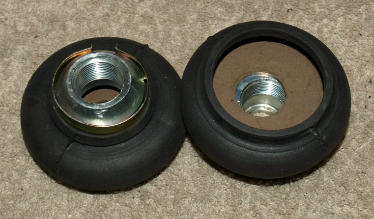
Alternator installed, note the wire tie location. - To plug up the old attachment hole in the center of the outer primary case, there is a bolt and washer in the fastener kit
that will screw into your old chaincase attachment nut. The bolt and its washer go through the case from the inside and the
attachment nut and its washer thread into them.
The bolt and washer inside the case. 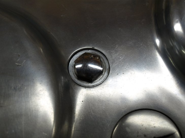
The attachment nut and washer on the outside. -
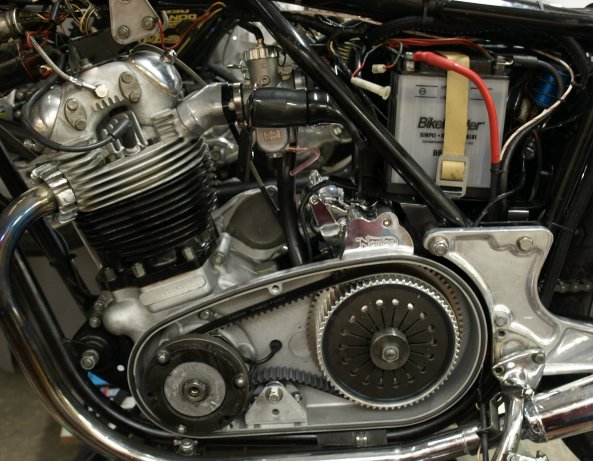
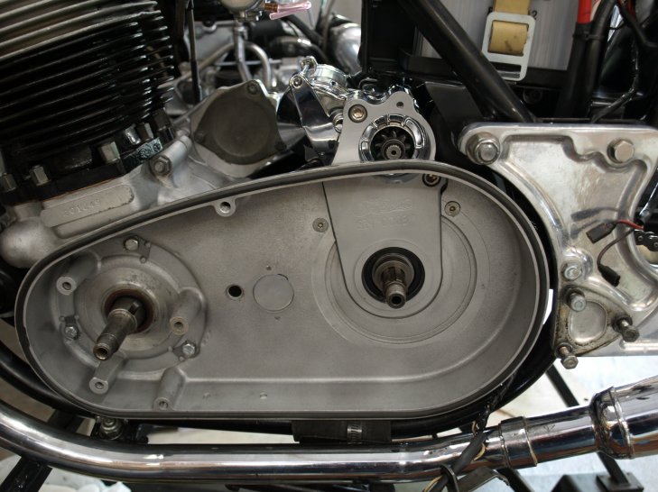
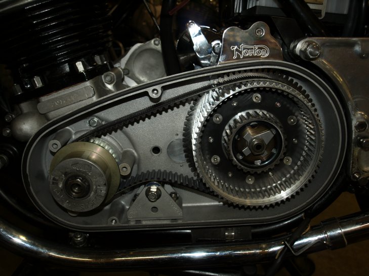
Completion of the fifth phase except for mounting the outer primary cover. 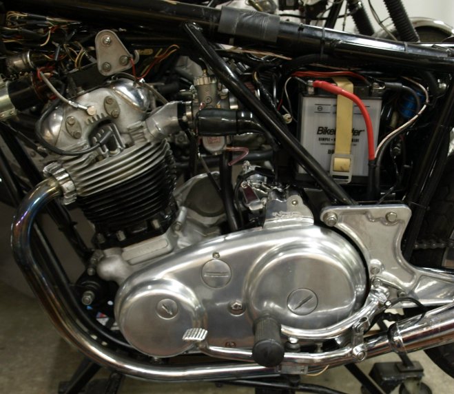
Completion of the fifth phase with the outer primary cover.
Sixth Phase - The sixth phase will complete the installation by re-installing all the parts that were removed in phase one. See the sixth phase check list Final steps to complete the installation for more detail on this phase. The order that you re-install all the parts removed is not important, but we will list what parts may give you trouble.
- Install the horn before you install the rear wheel.
- Install the rear chain tensioner bolts into the swingarm before you install the rear wheel.
- You may need to slightly bend the oil line pipes to clear the starter motor. This can be easly done by placing a long 5/16"
bolt into the oil pipes and very carefully bending them. One finger is all the force required to gently bend the pipes.
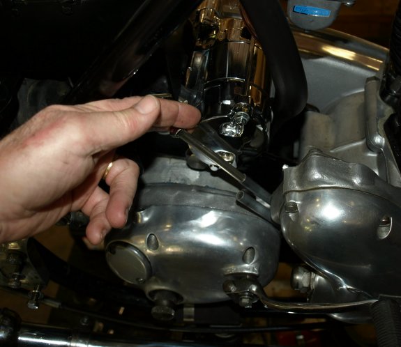
Bending the oil pipes to clear the starter. - Because we have seen several oil tanks crack on the bottom we do not use the bottom tank bolt on the stock oil tanks that do not have a re-inforced bottom. Instead we use a rubber pad on the bottom of the tank, slightly thicker than the bottom mounting boss. This pad is placed around the lower mounting boss, so the tank can move with vibrations. The oil lines and the top two mounts will hold the tank in place
- Due to the fact that the MK3 engine cradle is being use for this starter conversion;
if you have a 750 center stand, you will have to enlarge the mounting holes in the center stand to 11/16".
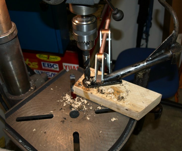
Drilling out the center stand. The best way to modify the 750 center stand is to drill out the hole by clamping the stand to a drill press. The problems with drilling the stand by hand, is you will get chatter and might not get a round hole. Instead of drilling the hole, the hole can be carefully filed so the new spacers fit snugly, but rotates freely.
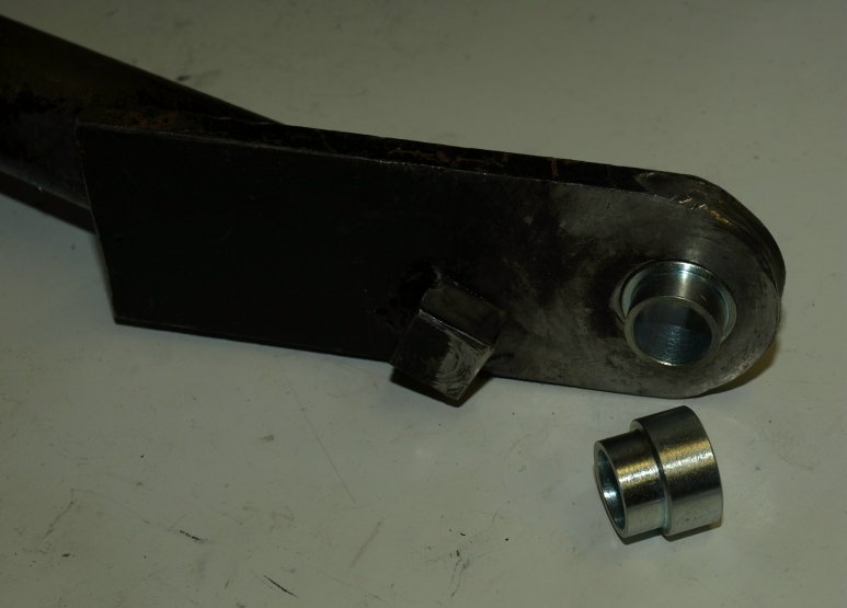
How the spacer fits into the center stand.
Return to Old Britts home page ….. Our Products, Ordering
This page was written and designed by F. H. Eaton & Associates if you have any questions or comments please contact us at infon@fheaton.com
- One red #4 gauge wire that connects the power to the starter.